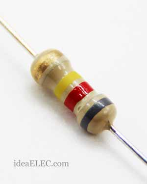
 مقاومت Through Hole
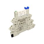
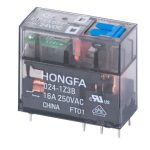 رله ها
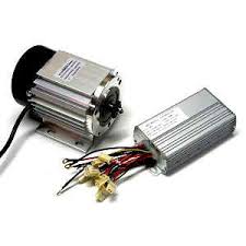 موتور و درایور
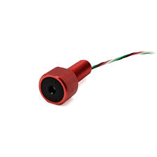
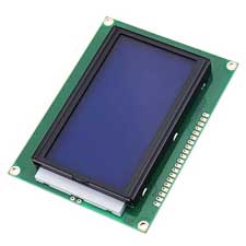 نمایشگرها
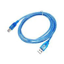 کابل usb
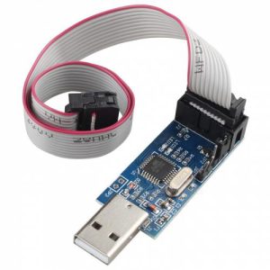
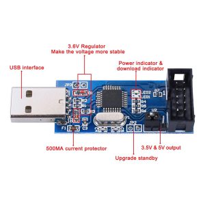


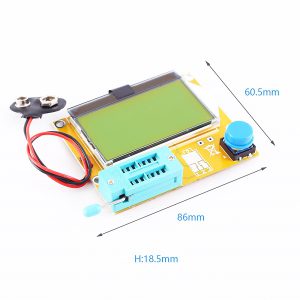
تستر قطعات الکترونیکی GM328A یک نمونه قدرتمند از تستر ها می باشد که دارای نمایشگر رنگی می باشد.
همچنین علاوه بر تست قطعات یک خروجی فرکانس مربعی.
یک ورودی ولتمتر و یک ورودی فرکانس متر نیز دارد.
تستر ترانزیستور چند منظوره برای تشخیص خودکار ترانزیستورهای JFET نوع NPN و PNP و همچنین MOSFET کانال N، کانال P ، دیودها، دیود دوگانه، تریستور، شناسایی خودکار پین اوت ترانزیستور. همچنین می تواند برای اندازه گیری فرکانس و ژنراتور سیگنال PWM استفاده شود.
توجه فرمائید :حتما قبل اتصال خازن ها برای تست از دشارژ بودن آنها مطمئن شوید تا دستگاه دچار آسیب نشود.
هنگام تست قطعات روی برد مدار، مطمئن شوید که برق را از برد مدار جدا کنید، قطعات دارای ولتاژ به ماژول آسیب خواهند زد.

مشخصات:
نمایشگر: 1.8 اینچ TFT رزولوشن 160×128 پیکسل
کنترلر نمایشگر: ST7735S
پردازنده: ATMega328P
ولتاژ کاری: 6.8 تا 12 ولت
جریان مصرفی: 30 میلیآمپر به ازای ورودی 7.5 ولت
شمارنده فرکانس: 1 هرتز تا 2.9 مگاهرتز
دقت شمارنده: 0.001 مگاهرتز
مولد فرکانس: تنظیم از 1 هرتز تا 2 مگاهرتز
مولد مدولاسیون عرض پالس(PWM): 10 بیت (1-99%) با فرکانس 7812.5 هرتز
اندازهگیری مقاومت: 0.1 اهم تا 50 مگااهم با دقت 0.1 اهم
اندازهگیری خازن: 25 پیکوفاراد تا 100,000 میکروفاراد
اندازهگیری سلف: 0.01 میلیهانری تا 20 هانری
قطعات سازگار: Thyristor, PNP, NPN, J-FET, TRIAC, Mosfet, Diode, Triac, LED
سنجش حسگر: DS18B20 و DHT11
دارای تشخیص خودکار نوع و قطب ترانزیستور
تشخیص میزان ESR خازنها
اندازهگیری ولتاژ شکست دیود زنر
اندازهگیری ولتاژ گیت و خازن گیت ماسفتها
تشخیص سلامت دیودهای ماوراء بنفش
ابعاد برد: 7.5 x 6cm / 2.95 x 2.36in
دانلود فایل مشخصات و راهنمای استفاده از تستر قطعات الکترونیکی Universal مدل GM328A
Description:
Multi-functional transistor tester for automatic detection of NPN and PNP transistors, N channel, P channel, MOSFET and JFET, diodes, dual diode, thyristor, automatic identification of the transistor pinout. It also can be used for frequency measurement and PWM signal generator.
Specifications:
Type: Assembled Tester
Display: 1.8inch 160*128 LCD
Input voltage: DC 6.8V-12V
Operating current: about 30mA, measured when inputting 7.5V DC voltage
Resistance measurement: Max. 50MΩ
Resistance resolution: 0.01Ω
Capacitance measurement: 25pF~100mF
Capacitance resolution: 1pF
Inductance measurement: 0.01mH~20H
PCB size: 7.5 x 6cm / 2.95 x 2.36in
Product weight: 50
Package size: Approx. 10 x 7 x 2cm / 3.94 x 2.75 x 0.8in
Package weight: 53g / 1.9oz
Features:
1. The processor uses high-performance single-chip ATMEAG328P DIP-28. With IC seat.
2. Display unit uses 160×128 pixel color display, the whole screen character number is 8×20, color depth is 16 bits, graphics display component symbol.
3. Rotary code switch control, one-button measurement, automatic shutdown.
4. Powered by a 9V laminated battery, it can also be powered by a power adapter. The current is about 30mA, and the current is about 20nA after shutdown.
5. Automatic detection of NPN and PNP transistors, FETs, diodes, dual diodes, thyristors, thyristors, automatic identification of the above transistor pin distribution.
6. Test NPN and PNP triode common emitter current amplification factor, base-emitter threshold voltage, collector-emitter leakage current at turn-off.
7. Identification of Darlington transistors through triode base-emitter threshold voltage and high current amplification factor.
8. Detect power diodes and FET built-in protection diodes.
9. Test FET gate-source turn-on threshold voltage, drain-source on-resistance, gate-source capacitance.
10. It can measure up to 2 resistors at a time, so the adjustable resistors of the three feet can also be measured. If the adjustable resistor is adjusted to the endpoint, only one resistance value can be measured.
11. For capacitors larger than 90nF, the equivalent series resistance (ESR) is measured at the same time. The resolution of the equivalent series resistance is up to 0.01Ω.
12. For capacitors larger than 5000pF, the voltage drop rate after charging is also displayed. This value can reflect the quality factor (Q value) of the capacitor.
13. Measure up to two diodes at a time, showing their positive and negative, on-voltage.
14. The LED is also shown as a graphical symbol of the diode, and its turn-on voltage is much higher than that of a normal diode.
15. A Zener diode with a reverse breakdown voltage of less than 4.5V can also be detected and displayed as a double diode symbol. The positive and negative poles have a diode symbol with a turn-on voltage of about 700 mV, and the turn-on voltage corresponding to the other diode symbol is a regulated value. So don’t measure a normal diode and a Zener diode simultaneously.
16. When testing a single diode, the reverse junction capacitance of the PN junction is tested at the same time. The PN junction capacitance of the transistor can also be tested. At this time, only the base and emitter of the transistor, or the base and collector can be placed at the same time.
17. Capacitors below 25pF can also be tested. This kind of test requires a 30pF capacitor. First test the 30pF capacitor. Then measure the capacitor to be tested in parallel and measure again. Subtract the measured value of the 30pF capacitor.
18. Measure the inductance simultaneously for resistors up to 2100Ω, measuring from 0.01mH to 20H.
19. The test process takes about 2 seconds, and large capacitors and inductors take longer.
20. The frequency measurement range is from 1 Hz to 1 MHz or higher. When the measured frequency is lower than 25 kHz, the period can be displayed with a resolution of 0.001 MHz.
21. DC voltage measurement up to 50V.
22. Output one channel square wave signal, multiple frequency options are available, the highest output frequency is 2MHz.
23. Output one channel fixed frequency, adjustable duty cycle pulse signal (PWM), duty cycle adjustment from 1% to 99%.
24. Separate capacitance test function, the test method is continuous measurement. For 2uF-50mF capacitors, it can be directly measured in its circuit. (The circuit where the measured capacitor is located must be powered off, and the measured capacitor needs to be completely discharged.)
25. Thyristors and thyristors can only recognize their pinouts, and also need to test the thyristor or thyristor with less trigger current than the tester can provide. The tester can only provide up to 6mA of trigger current.
26. Infrared remote control decoding and encoding support the encoding format of TC9012 and upD6121 chips
Notice:
Before measuring capacitance, the capacitor must be discharged, otherwise very likely damage the meter.
Be sure to disconnect the power from the circuit board when testing the components on the circuit board, the test equipment has residual voltage is not allowed.
Package includes:
1 x Transistor Tester
نقد و بررسیها
هنوز بررسیای ثبت نشده است.