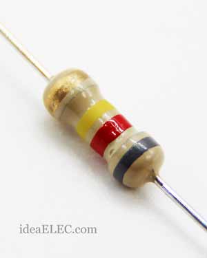
 مقاومت Through Hole
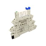
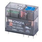 رله ها
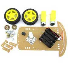
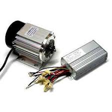 موتور و درایور
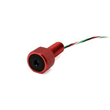
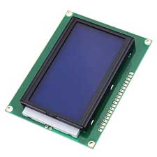 نمایشگرها
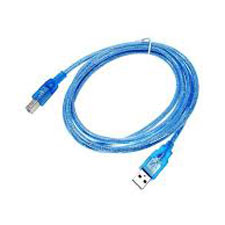 کابل usb


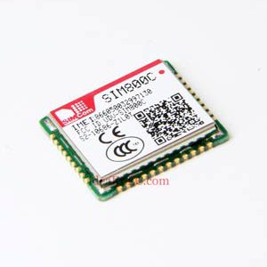
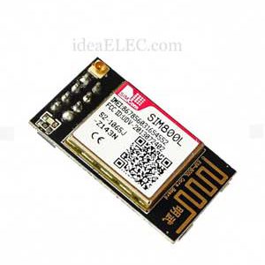
دانلود دیتاشیت SIM800L

NET pin is where you can solder the helical antenna that comes with the module.
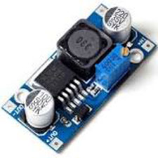
VCC is the power supply pin. Keep in mind that the SIM800L chip has an operating voltage range of 3.4 V to 4.4 V, so connecting this module to the Arduino’s 5V output is probably going to cause damage to the module. It doesn’t even run on 3.3 V! Use a Li-Po battery or a DC-DC buck converter instead.
RST (Reset) is the reset pin. If you got the module in an absolutely bad space, pull this pin LOW for 100ms to perform a hard reset.
RxD (Receiver) pin is used to send commands to the module. This pin is auto-baud so the baud rate at which you send the “AT” command after reset is the baud rate used.
TxD (Transmitter) pin transmits data from the module to the microcontroller.
GND is the ground pin.
RING pin is the Ring Indicator. This is basically the ‘interrupt-out’ pin from the module. It is by default HIGH and can be configured to go LOW when a call or SMS is received.
DTR pin controls the sleep mode. Pulling it HIGH causes the module to enter sleep mode, disabling serial communication. Pulling it LOW for approximately 50 ms will wake up the module.
MIC± is a differential microphone input. You can connect an external electret microphone to these two pins directly.
SPK± is a differential speaker interface. You can connect a speaker to these two pins directly.

محسن فراهانی –
سلام
لطف می کنید دیتاشیت خود ماژول هم بذارید
محمد حسن خانی (خریدار محصول) –
سلام
توضیحات و دیتاشیت اضافه شد